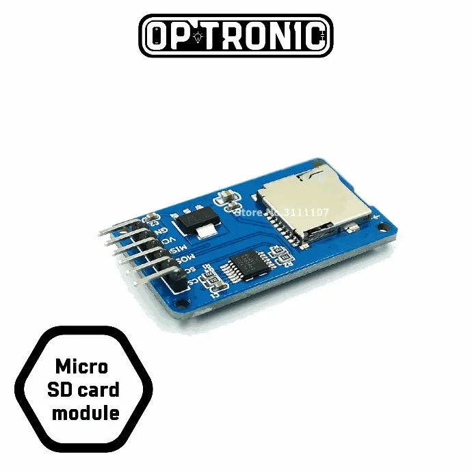
Description
The module of the reader of micro SD cards with goldpin connectors – 2.54 mm pitch. It communicates with the main board via SPI interface. It works with a supply voltage from 3.3 V to 5 V.

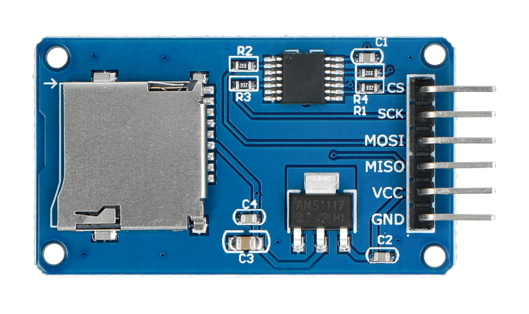
Pin Configuration of Micro SD Card Adapter Module
The module contains 6 pins for power and communicating with the controller. The table below describes the pin type and role of each pin on the module.
| Pin Type | Pin Description |
| GND | Ground |
| VCC | Voltage Input |
| MISO | Master In Slave Out(SPI) |
| MOSI | Master Out Slave In(SPI) |
| SCK | Serial Clock(SPI) |
| CS | Chip Select(SPI) |
Sensor maintenance
The SD card communicates using the SPI bus. Most of the microcontrollers, including those used in Arduino, AVR,have hardware to verify this interface.
| The product is compatible with STM32 The module works with the built-in examples in the Arduino IDE. |
Specification
- Supply voltage: 4.5 V to 5.5 V
- Integrated voltage regulator: 3.3 V on SPI pins
- Current: about 80mA
- Interface: SPI
- Pins’ pitch: 2.54 mm
- Mounting holes M2: spacing of 38 mm and 20 mm
- Module dimensions: 42 x 24 mm
Applications of Micro SD Card Adapter Module
Here are some of the applications of the Micro SD Card Adapter Module.
- Data loggers
- Audio, Video storage, and Visualization
- Expandable memory